×
- Hello
- Login or Register
- Quick Links
- Live Chat
- Track Order
- Parts Availability
- RMA
- Help Center
- Contact Us
- Shop for
- Honda Parts
- Honda Accessories

My Garage
My Account
Cart
Genuine Honda Fit Relay
Wire Relay- Select Vehicle by Model
- Select Vehicle by VIN
Select Vehicle by Model
orMake
Model
Year
Select Vehicle by VIN
For the most accurate results, select vehicle by your VIN (Vehicle Identification Number).
11 Relays found

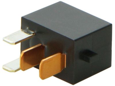
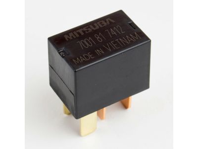
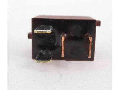
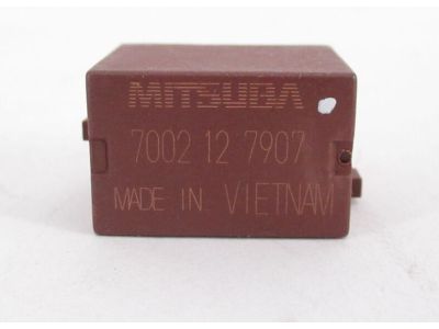
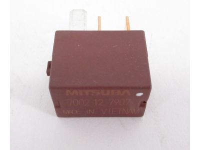
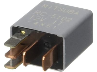
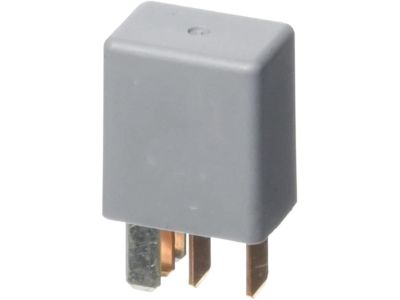
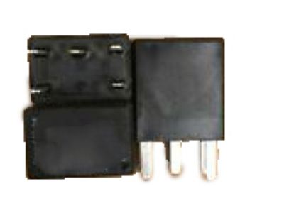
Honda Fit Relay Assembly, Power (Micro Iso) (Mitsuba)
Part Number: 39794-SDA-A05$22.62 MSRP: $32.22You Save: $9.60 (30%)
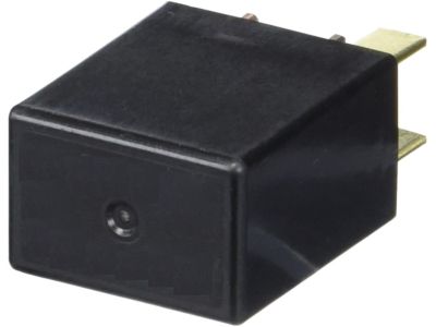
Honda Fit Relay Assembly, Power (Micro Iso) (Omron)
Part Number: 39794-SDA-A03$22.81 MSRP: $32.22You Save: $9.41 (30%)
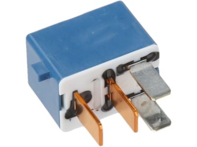
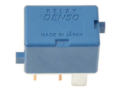
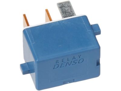
Honda Fit Relay Assembly, Engine Control Module (Denso)
Part Number: 39794-SDA-902$63.62 MSRP: $92.20You Save: $28.58 (31%)
Honda Fit Relay Assembly, Fuel Pump (Denso)
Part Number: 39794-SDA-004$50.52 MSRP: $71.35You Save: $20.83 (30%)
Honda Fit Relay Assembly, Power (5P) (Micro Iso) (Mitsuba)
Part Number: 39794-S10-003$46.35 MSRP: $65.47You Save: $19.12 (30%)
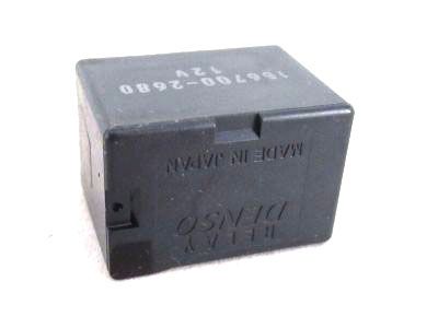
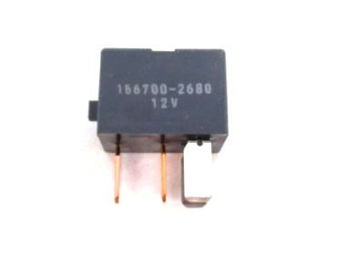
Honda Fit Relay Assembly, Power (Micro Iso) (Denso)
Part Number: 39794-SDA-A02$29.16 MSRP: $41.53You Save: $12.37 (30%)
Honda Fit Relay Assembly, Power (4P) (Micro Iso) (Matsushita)
Part Number: 39794-S04-014$47.88 MSRP: $67.63You Save: $19.75 (30%)
Honda Fit Relay Assembly, Power (Micro Iso) (Denso)
Part Number: 39794-T5A-J01$37.19 MSRP: $52.53You Save: $15.34 (30%)Honda Fit Relay Assembly, Power (5P) (Micro Iso)
Part Number: 39794-SNB-E01$37.11 MSRP: $52.42You Save: $15.31 (30%)

Honda Fit Relay
In search of affordable OEM Honda Fit Relay? Consider browsing through our extensive inventory of genuine Honda Fit Relay. Not only do we provide market-leading prices and a manufacturer's warranty, but we also pride ourselves on exceptional customer service and swift delivery.
Honda Fit Relay Parts Questions & Experts Answers
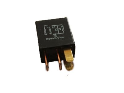
- Q: How do relays function in electrical systems and how can they be tested for defects on Honda Fit?A:Some of the electrical feature in the pne we have the fuel injection system, Horns, starter, and the fog lamps among others, use relays to convey electrical signals to the various parts. Relays have a low current control circuit to switch ON/OFF a high current power circuit; if a relay fails, the related component will be ineffective. Apart from engine and interior fuse/relay boxes, most relays are situated and if suspect output relay is sensed, it must be pulled out and tested through a procedure or be referred to a dealer service or a repairer shop to be replaced in case the relays are defective they must be replaced as a single unit. The general relays employed are the ISO relays with terminals marked with numbers to show the circuits and their roles, and are categorized by two terminal configurations. The control circuit terminates on the coil while the terminals of the power circuit are connected to the coil. When energized, the coil produces a magnetic field to make the larger contact of the power circuit to close in order to allow the circuit loads to be supplied with power. In most cases, the two terminals 85 and 86 constitute the control circuit; however, if there is a diode, terminal 86 is connected to the battery positive voltage and the terminal 85 to the ground; if there is only a resistor terminal 85 and terminal 86 may be connected in either direction. Terminal 30 is mainly associated with the battery voltage supply for circuits and terminal 87 is associated with the ground of the circuit. In order to verify the relay, an ohmmeter can be used in testing-making sure to connect the meter according to the polarity-and reversing the leads to give a second test on the continuity of the relay control coil. This is because, if a resistor is present it must have equal resistance whether in reverse or forward use, while a diode shall have relatively high resistance to the forward use as compared to the reverse use. When there is an infinite resistance in both directions, then it is recommended that the relay be substituted. After removing the relay, there should be no continuity between two terminals of the power circuit, and the capacitor should not remain connected when capacitive or inductive loads are switched off, so there will be no continuity between terminal 30 and 87 when de-energised. By touching one end of the fused jumper wire at terminal 86 and other end to positive terminal of the battery and another jumper wire to terminal 85 to ground, the relay should emit a clicking sound. Once the jumper wires are connected, continuity should be present in between terminals 30 and 87. Any relay not passing these tests should be replaced.
