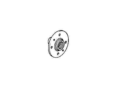
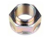
Push the lock tab in the anti-clockwise direction away from the spindle and turn the nut counterclockwise to a half turn, and also slightly turn the lug nuts in the anti-clockwise direction. Lift the front of car and put it on the safety stands before removing the front wheel and the spindle nut. Take out the bolts which fix the brake caliper to the knuckle and pull the caliper away from it but it should be suspended by a wire. If available, unscrew the disc brake rotor nuts then thread in the two 8 x 1.25 x 12mm disc brake removal bolts and turn them to send the rotor away from the hub about two turns at a time in order not to cock them. The removal of the tie rod from the knuckle can be done by use of a tie rod end removal tool without harming the ball joint seals. Place the lower control arm on the jack and then remove the cotter pin that is beneath the lower arm ball joint, then, take off the castle nut of the lower control arm making sure that the jack is well positioned beneath the lower control arm ball joint to avoid any unwanted movement. Turn the lower arm ball joint nut to the right down to the half thread of the joint then disconnect the ball joint and lower the arm by applying a puller. Take off the knuckle protector; then unbolt the cotter pin and the upper ball pin nut; finally, employ the ball joint remover to disengage the upper ball joint from the knuckle. Free the four nuts on top of the shock engaging the knuckle by turning the free of the nut clockwise and the other anti-clockwise and remove the knuckle by striking the top of the knuckle lightly with a hammer. If they are still in place, to free the assembly it is pulled off the driveshaft, then to separate the hub from the knuckle, various tools and hydraulic press are employed. The splash guard and snap ring have to be removed then by means of special tools and hydraulic press the bearing outer race of the knuckle has to be pressed. The outboard bearing inner race can be pulled out using a bearing puller and always, whenever you pull off a hub, take along the wheel bearings and outer dust seal. It is for this reason that all the old grease should be cleaned out from the driveshafts and spindles and the hub and knuckle as well, and all parts must be well dried and wiped. Fix the bearings-on the knuckle-using the bearing outer race installing tool and the installing base tool: install the snap ring and splash guard next. Put the hub in the special tool fixture, arrange the knuckle in the position on the press and apply the force downwards. The other steps as follows are the reverse of the removal procedure with new spindle nut and staking after torquing them. Snug the shock pinch bolt with 47 ft. lbs. (65 Nm) with the ball joint nut to 32 ft. lbs. (44 Nm). For 1988-91 models never try to tighten or to loosen any spindle nut with out the car standing on the four wheels due to high torque that may lead to fall of the vehicle. Pull the spindle nut stake apart from the spindle and unscrew the nut, lift the car and provide it with a support. Loosen and take off the wheel and tire assembly, including the spindle nut, followed by the caliper mounting bolts to this remove the caliper and suspend it on a wire. Take out the six 6mm brake disc retaining screws, then install two 8 x 1.25 x 12mm bolts into the disc to push the disc away from the hub, turning those bolts, each two turns at one time so as not cock the other three. Undo the cotter pin on the tie rod Castle nut then serrated nut, to disconnect the tie rod ball joint using an appropriate remover after which you pull out the tie rod from knuckle. Cotter pin has to be made removed and the ball joint to the lower arm nut loosened half way down the joint threads then the ball joint and lower arm to be separated with the help of an appropriate puller while at the same time avoiding damaging the ball joint boot. If required then use penetrating lubricants so that the ball joint may be loosened up. To do this you need to take off the knuckle protector, cotter pin and the upper ball pin nut, this will help you separate the upper ball joint and the knuckle. Pop off the knuckle and hub from the half shaft, in addition, the splash guard screws must be removed from the knuckle. Place the knuckle/hub assembly on a hydraulic press, the hub should be pressed out from the knuckle with a suitable driver with the knuckle being supported on a suitable base, Also when removing this bearing, a new one has to be fitted. Unlock the 76mm snap ring and the knuckle ring then push the wheel bearing out of the knuckle with a suitable driver while you hold the knuckle. Pull off the outboard bearing inner race from the hub using a suitable bearing puller. Before refitting clean both the knuckle and hub well and whilst supporting the knuckle press a new wheel bearing into the hub using a suitable driver. Locate and properly place the 76mm snap ring into the knuckle groove, the splash guard should then be put in and the screws should be tightened to 7 ft lbs. (10 Nm). Insert the knuckle in the press on the hydraulic press then press on the hub with the help of a Suitable driver, do not press with the maximum force of the hydraulic press beyond 2tons. Place the front knuckle ring on the knuckle and then mount the knuckle/hub assembly in the reverse manner in which it was removed, with the UTN and TTN being tightened to 32 ft. lbs. Everyone that has been a part of a vehicle assembly line knows that torque specifications range from the upper ball joint castle nut at 44 Nm to the lower ball joint castle nut to 40 ft. lbs. (55 Nm). After ensuring that all the four wheels are touching the ground tighten the spindle nut to 134 ft. lbs. (185 Nm).
Posted by HondaPartsNow Specialist 
